This is part of my project to understand the IR protocol and try to decode IR signals that being send from my AC’s remote to the AC itself. So that the idea is: If I can figure out the different IR signals that being that transmitted, then I should be able to replay the traffic and control the Aircon from my PC or use my own custom IR hub instead of sending data to some third party – Alexa or Google Assistant. This may be applicable on other devices as well that use an IR transmitter/receiver like a TV/remote controlled fan/hubs.
Disclaimer: I am no means an electronics expert. This is just me experimenting and playing around trying to make sense of how IR works with no prior knowledge of how the protocol works. If you are electronics expert, then this post is probably not for you are better off pressing CTRL+W on your keyboard.
Requirements:
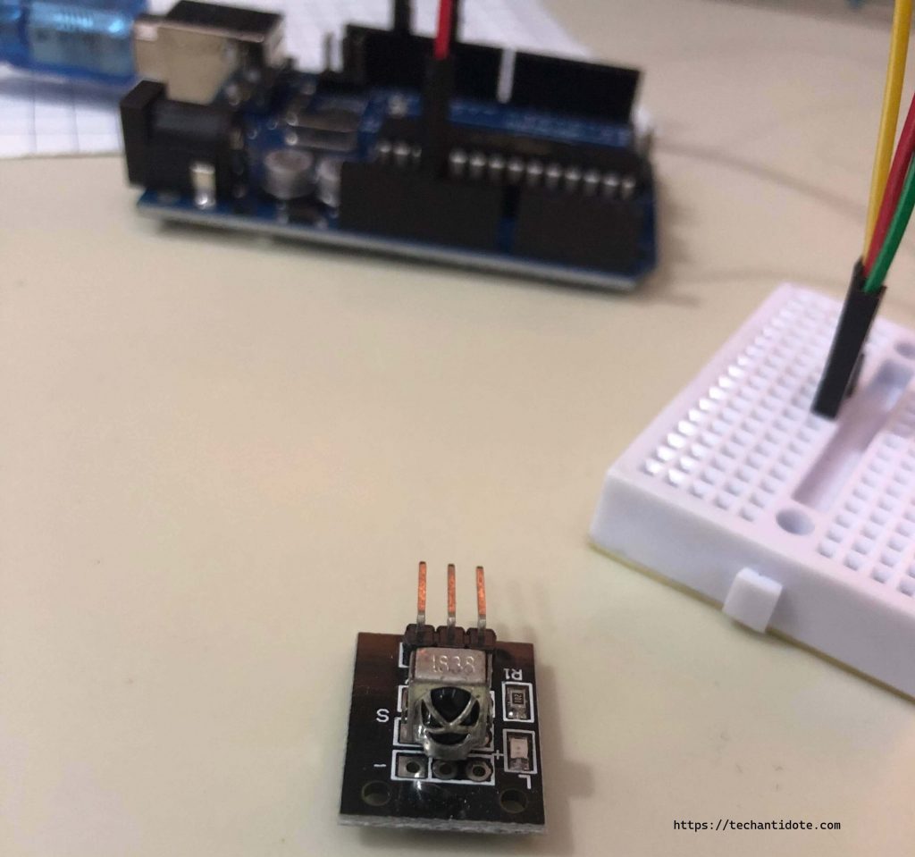
- KY-022 Infrared Receiver (38kHz)
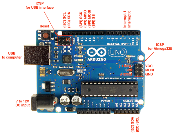
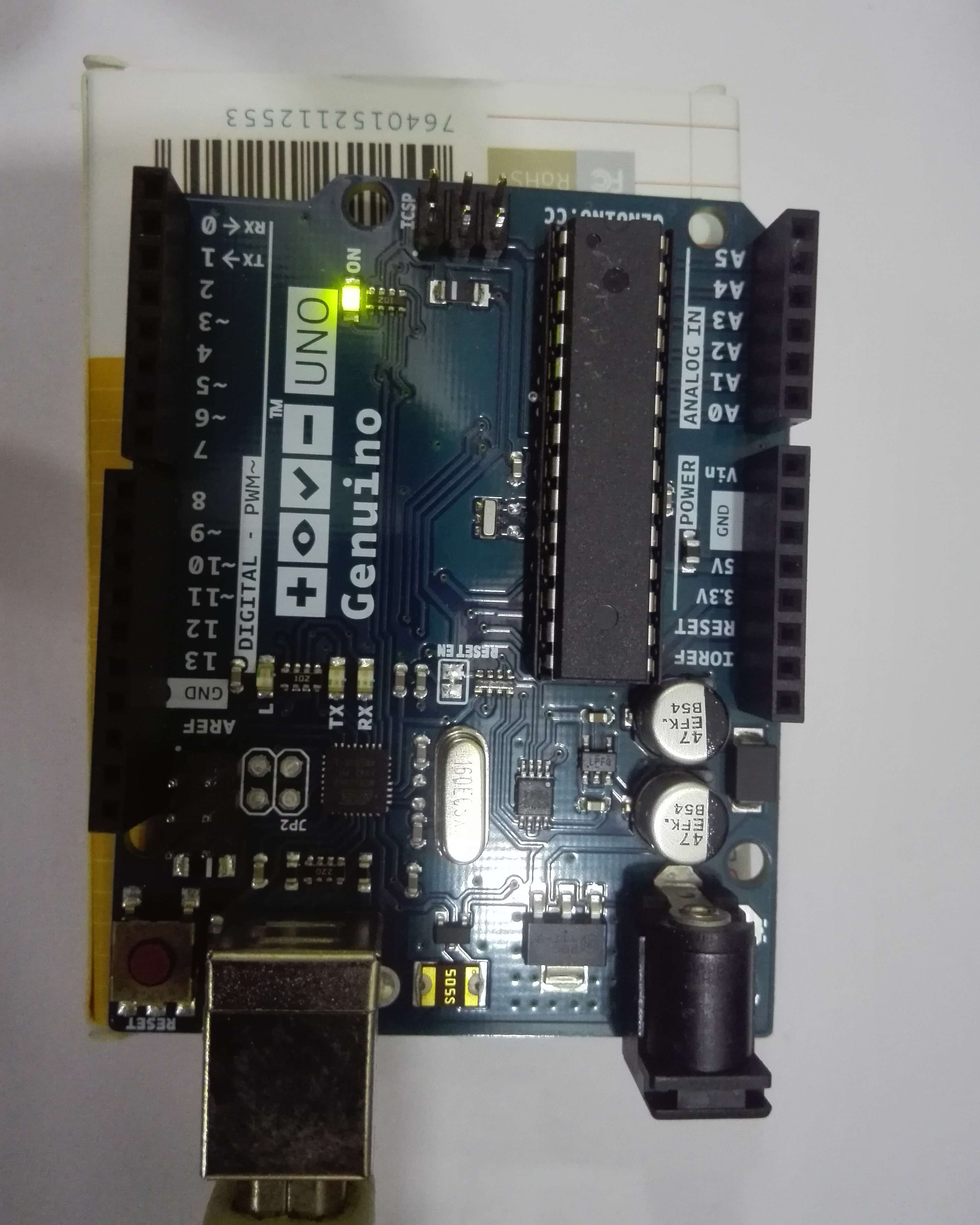
- Arduino UNO U3
- Breadboard
- 3x Male to Male Jumper Cables.
- Arduino ID with IRremote library installed (Link)
- Computer to write your code. Duh!
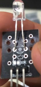
Here is a picture of the KY-22 IR receiver.
Circuit Connection:
Connect pin labelled “Y” on the KY-022 to Pin 11 on the Arduino
Connect pin labelled G to GND pin on the Arduino
Connect pin labelled R pin to the 5V pin on Arduino
-Below is the source for the IR decoder:
#include <IRremote.h>

int RECV_PIN = 11; // define input pin on Arduino.
IRrecv irrecv(RECV_PIN);
decode_results results; // decode_results class is defined in IRremote.h

IRsend irsend;

void setup() {
  Serial.begin(9600); // Set Serial monitor baud rate
  irrecv.enableIRIn(); // Start the receiver
}

void loop() {

  if (irrecv.decode(&results)) {
    Serial.println(results.value, HEX);
    irrecv.resume(); // Receive the next value
  }

  delay(1000);

}
Upload the code to the Arduino and then navigate to Tools>Serial Monitor.
Now point your IR remote to the IR receiver sensor and press any key in the remote. Now, you should see the HEX value that was send from the remote in the serial console.
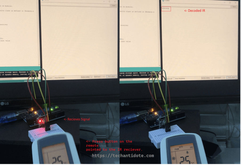
For example, a test case I pointed my AC’s remote to the IR receiver(KY-022) and pressed the power button. This result printed on the Serial Monitor was HEX value 90900E0A. Note: While pressing the power On button, the remote had 25 degrees set.
Here is a sample screenshot of the setup.
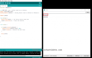
Here is a screenshot of the source and the data from the serial session.
Similarly when pressing the Power Off button in the return, a different IR code of 80900C0A was send.
Hell Yeah!!!!! Ok, maybe I got excited bit too much.
I know this probably sounds dumb, but I did notice something interesting on how this is all put together. So, lets say the temperature of the AC in the remote is set to 16C. Now, if I press the “+” button to increase the temperature to 17C, then I see a different code and if I press it again again, I see a different code being send.
Here what the different hex codes for different temperatures look like(used by pressing the increment/+ sign on the remote):
Temp 16: 90000E0A
Temp 17: 90800E0A
Temp 18: 90400E0A
Temp 19: 90C00E0A
Temp 20: 90200E0A
Temp 21: 90A00E0A
Temp 22: 90600E0A
Temp 23: 90E00E0A
Temp 24: 90100E0A
Temp 25: 90900E0A
Temp 26: 90500E0A
Temp 27: 90D00E0A
Temp 28: 90300E0A
Temp 29: 90B00E0A
Temp 30: 90700E0A
Trying to make sense of IR (Sort Of):
So, in a programming point of view, I was expecting something like “new temperature” = “current temperature” + 1 and then set the value rite? Well this sort of the same with a slight difference which I guess is the way IR protocol works. So, the handheld IR remote has some logic in itself. Here is my assumption of what is happening.
- Say, the handheld IR remote for the Air Conditioner has current temperate as 16 degree Celsius (16C).
- Now lets say the user, clicks the + sign on the AC remote (IR transmitter) to increase the temperature from 16C to 17C. The IR device knows the old value as 16 from its on-board memory and now knows the new temperate has to be set to 17C. So here, the arithmetic operation i.e. increment is done on the client side i.e on the IR remote itself.
- The IR remote has a hard coded value of 17C somewhere in its code. The remote simply sends the IR signal with IR code for 17C. I.e. It will send 90800E0A to the IR Receiver.
- The IR receiver (in this case the AC), receives the IR code for 17C and then sets the temperature to 17C. Here, the AC has hardcoded values for each IR code for each temperature in its code. Something like: If “IR code received” == “90800E0A“, then set temperature to 17C.
- It looks more like each temperate value is hard coded and the IR remote has these values hard-coded.
Next, I will need to learn how to get a IR transmitter and replay these codes so that I can control my Aircon and other electronics from my PC. Maybe create a DIY IR hub and hook it to my PC?
So, I did buy a IR transmitter to replay the signals but the transmitter that I received was DOA. Well that went well. Haha!
Anyways, will probably order a new transmitter to test this out post the whole COVID-19 shiZstorm.
Regards.
ΞXΤЯ3МΞ
Sources/Credits/References:
PS: Credits to Arduino modules for making it super simple to understand this. Below are credits/resources that helped out.
Arduino Modules.info
IR-Project
Duino4projects
Sparkfun
Robojax